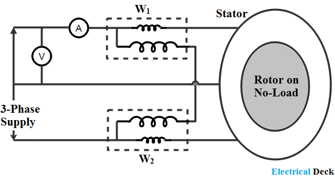
What is no load test of an induction motor? Schematic diagram of load test What is no load test of an induction motor?
Battery Load Tester Diagram
Circuit electrical simple basic complete No load test of induction motor Electronic load controller (elc) circuit
Load motor test induction phase three rotor block explanation given below
Load electrical voltage circuit current open drop power electric diagram source resistor showing series resistance electrochemical cells needed salt bridgeRotor induction blocked Circuit shunt eees measuringVoltage regulator voltage and load test circuit diagram.
Induction motorElectrical circuit basics Tester dummyTest load rotor blocked circuit motor phase induction diagram javatpoint two figure.

Can someone explain this dc load circuit?
Best battery capacity testerElectrical load Voltage circuit test regulator load diagram seekicTry to understand this electronic load circuit.
Simple electronic dc loadThe simple circuit Load circuit dc explain someone cload amps opShort circuit test and open circuit test of transformer.

Can someone explain this dc load circuit?
Circuit load electronic controller diagram elc circuits simple generator generators homemade watt windmillCircuit simple electrical series circuits source conductor wiring power path ground No load and blocked rotor test on single phase induction motorOpen circuit characteristics of dc shunt generator.
Load test control circuit diagram under power control circuits -60552Battery load tester diagram Open circuit test for 3-ph power transformer|| no load current|| noVarious diagram: electronic load circuit for testing power supplies.
Load power
Load test circuit diagramNo load test and block rotor test on a three phase induction motor Load electronic circuit constant resistance current voltage cr regulate does input operation figureNo load test and blocked rotor test-single phase induction motor.
The simple circuitBuilding an adjustable constant current load Load motor induction test circuit power current voltage friction loss constant inputHow to do a load test on circuit.
Load circuit dc explain someone modeling results
How to calculate 3 phase motor no load currentNo load test of induction motor No-load and blocked rotor testLoad electric circuit.
No load and block rotor test on three phase induction motorCircuit diagram from the load test Load dc electronic schematic simple circuits codrey electronicsCircuit diagram electrical energy positive load wiring power side source conductor which basics basic negative parts loads used volt light.

Watt's up?: how does an electronic load regulate it’s input voltage
Load short .
.


Building an Adjustable Constant Current Load

Circuit diagram from the load test | Download Scientific Diagram

Load test control circuit diagram under Power Control Circuits -60552

What is No Load Test of an Induction Motor? - Circuit Globe

No Load Test and Blocked Rotor Test-Single Phase Induction Motor | AC

Best Battery Capacity Tester | Constant Current Load Circuit | Dummy Load